
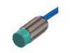


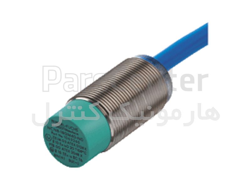
سنسور NCN8-18GM40-N0
سنسور نامور (NAMUR) مدل NCN8-18GM40-N0 از سنسورهای با تغذیه 8 ولت پپرل فوکس آلمان میباشد که قابلیت سنس تا 8 میلیمتر را داراست.ویژگی خاص سنسورهای نامور EX بودن یا کاربرد در مناطق انفجاری و خطرناک میباشد.از این سنسورها در مناطق HAZARDOUS AREA با گازها،بخار گازها و غبار گازها استفاده میگردد.قطر این سنسور نامور 18 میلیمتر است و دارای CATEGORY 1G; 2G; 3G; 1D; 3D میباشد.
اطلاعات تامین کننده
هارمونیک کنترل نمایندگی PEPPERL+FUCHS ایران
تهرانوارد کننده، عمده فروش، خرده فروش، خدمات
نمایندگی PEPPERL+FUCHS، نمایندگی MTL، بریر پپرل فوکس، نمایندگی ACREL، بریر MTL، نمایندگی NOVUS، سنسور پپرل فوکس، بریر pepperl+fuchs، نماینده رسمی شرکت PEPPERL+FUCHS، سنسور pepperl+fuchs، نمایندگی IFM، رله PEPPERL+FUCHS، فروش بریر PEPPERL+FUCHS، فروش سنسور پپرل فوکس، نمایندگی پپرل فوکس، نمایندگی SICK
مشخصات
- شرکت سازنده
- PEPPERL+FUCHS
- مدل
- NCN8-18GM40-N0
- کشور سازنده
- آلمان
- نوع خروجی
- NAMUR NC
- ولتاژ تغذیه
- 8 ولت
- نوع اتصال
- کابل2 متری از جنس PVC
- جنس بدنه
- Stainless steel 1.4305 / AISI 303
- فرکانس سوییچینگ
- 300 هرتز
- دمای کاری
- 40- تا 100 درجه سانتیگراد
- قطر بدنه سنسور
- 18 میلیمتر
- میزان سنس
- 8 میلیمتر
- Category
- 1G; 2G; 3G; 1D; 3D
- درجه حفاظتی
- IP67
توضیحات محصول
Inductive sensor NCN8-18GM40-N0
- 8 mm non-flush
- Stainless steel housing
- Usable up to SIL 2 acc. to IEC 61508
Inductive sensor NCN8-18GM40-N0- 8 mm non-flush
- Stainless steel housing
- Usable up to SIL 2 acc. to IEC 61508
- Datasheet
- Documents
- CAD+CAE
- Approvals+Certificates
Download the complete datasheet as a PDF:
ENGCESENGFRADEUITAPOLPORRUSSPASWE中文
Datasheet excerpt: Technical data of NCN8-18GM40-N0General specifications Switching function Normally closed (NC) Output type NAMUR Rated operating distance 8 mm Installation non-flush Assured operating distance 0 ... 6.48 mm Actual operating distance 7.2 ... 8.8 mm typ. 8 mm Reduction factor rAl 0.42 Reduction factor rCu 0.4 Reduction factor r304 0.72 Nominal ratings Nominal voltage 8.2 V (Ri approx. 1 kΩ) Switching frequency 0 ... 300 Hz Hysteresis 1 ... 15 typ. 5 % Reverse polarity protection reverse polarity protected Short-circuit protection yes Current consumption Measuring plate not detected min. 3 mA Measuring plate detected ≤ 1 mA Switching state indicator all direction LED, yellow Functional safety related parameters MTTFd 2040 a Mission Time (TM) 20 a Diagnostic Coverage (DC) 0 % Compliance with standards and directives Standard conformity NAMUR EN 60947-5-6:2000
IEC 60947-5-6:1999Electromagnetic compatibility NE 21:2007 Approvals and certificates FM approval Control drawing 116-0165 UL approval cULus Listed, General Purpose CSA approval cCSAus Listed, General Purpose CCC approval CCC approval / marking not required for products rated ≤36 V Ambient conditions Ambient temperature -25 ... 100 °C (-13 ... 212 °F) Storage temperature -40 ... 100 °C (-40 ... 212 °F) Mechanical specifications Connection type cable PVC , 2 m Core cross-section 0.75 mm2 Housing material Stainless steel 1.4305 / AISI 303 Sensing face PBT Housing diameter 18 mm Degree of protection IP66 / IP67 Cable Bending radius > 10 x cable diameter Equipment protection level Dc (tc) Instruction Manual electrical apparatus for hazardous areas Device category 3D for use in hazardous areas with combustible dust Certificate of Compliance PF 15CERT3774 X CE marking [*PD-Z02585A*] ATEX marking II 3D Ex tc IIIC T80°C Dc
The Ex-related marking can also be printed on the enclosed label.Standards EN 60079-0:2012+A11:2013, EN 60079-31:2014
Protection by enclosure "tc" Some of the information in this instruction manual is more specific than the information provided in the datasheet.General The corresponding datasheets, declarations of conformity, EC-type examination certificates, certifications, and control drawings, where applicable (see datasheets), form an integral part of this document. These documents can be found at www.pepperl-fuchs.com. The maximum surface temperature of the device was determined without a layer of dust on the apparatus. Some of the information in this instruction manual is more specific than the information provided in the datasheet. Installation, commissioning Laws and/or regulations and standards governing the use or intended usage goal must be observed. If the Ex-relevant identification is printed exclusively on the adhesive label provided, this label must be affixed in the immediate vicinity of the sensor! The background surface to which the adhesivelabel is to be applied must be clean and free from grease! The applied label must be durable and remain legible, with due consideration of the possibility of chemical corrosion! Maintenance No changes can be made to apparatus, which are operated in hazardous areas.
Repairs to these apparatus are not possible.Special conditions Minimum series resistance RV A minimum series resistance RV is to be provided between the power supply voltage and the proximity switch in accordance with the following list. This can also be assured by using a switch amplifier. Maximum operating voltage UBmax The maximum permissible operating voltage UBmax must be restricted to the values given in the following list. Tolerances are not permitted. Maximum permissible ambient temperature TUmax Values can be obtained from the following list, depending on the max. operating voltage Ub max and the minimum series resistance Rv. at UBmax=9 V, RV=562 Ω 61 °C (141.8 °F) using an amplifier in accordance with EN 60947-5-6 61 °C (141.8 °F) Protection from mechanical danger The sensor must not be exposed to ANY FORM of mechanical danger. Protection from UV light The sensor and the connection cable must be protected from damaging UV-radiation. This can be achieved when the sensor is used in internal areas. Protection of the connection cable The connection cable must be prevented from being subjected to tension and torsional loading. Electrostatic charge Electrostatic charges must be avoided on the mechanical housing components. Dangerous electrostatic charges on the mechanical housing components can be avoided by incorporating these in the equipotential bonding. Do not attach the nameplate provided in areas where electrostatic charge can build up. General information Use in the hazardous area see instruction manuals Category 1G; 2G; 3G; 1D; 3D